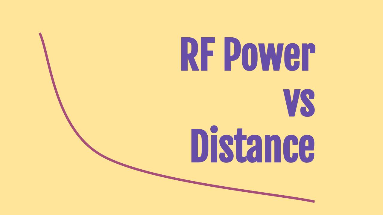
In this post we provide a calculator to find the RF power (in dBm or Watt) as a function of distance away from the source.
Calculator
Enter
- Transmit Power Pt (select the appropriate units of Watt or dBm)
- Frequency of operation f
- Distance d
- Transmit Antenna Gain GTx
- Receive Antenna Gain GRx
The tool will provide the receive signal power in Watt or dBm
Example Calculation
Consider a 1 Watt transmitter operating at 915 MHz. At a distance of 100 meters, the received signal power is 6.79*10-8 Watt. This is equivalent to -42 dBm.
When the distance increases to 1000 meters, the received signal strength is further reduced to 6.79*10-10 Watt or -62 dBm.
The received power of an RF signal drops exponentially with increasing distance.
Background
The power of a radio frequency signal decreases as the distance from the transmitter increases
As the power decreases it becomes more difficult to receive and process the signal.
This relationship between transmit and received power is given by the Friis Transmission Equation for free space propagation and considerations involving real-world environments.

Friis Transmission Equation
In free space, the Friis Transmission Equation provides a model for understanding how the power of an RF signal decreases with distance. The equation is:
Pr = (Pt*Gt*Gr*λ2)*(1/(4π*d2))
Where:
- Pr is the power received,
- Pt is the power transmitted,
- Gt is the gain of the transmitting antenna,
- Gr is the gain of the receiving antenna,
- λ is the wavelength of the RF signal,
- d is the distance between the antennas.
The equation above shows that the received power (Pr) decreases with the square of the distance (d2) between the transmitter and receiver. This means that doubling the distance between the transmitter and receiver results in only one-fourth of the received power, under ideal free space conditions.
Note that this equation only applies in the far field of the antenna. In other words, d >> λ. It is sufficient if the distance between the two antennas is at least 10 times larger than the wavelength.
Practical Considerations
In real-world environments, factors such as obstacles, atmospheric conditions (specially at higher frequencies), and interference can further complicate the relationship between RF power and distance. These factors can lead to additional losses not accounted for by the Friis Transmission Equation, including:
- Absorption Losses: Materials like walls, trees, and buildings can absorb RF energy, reducing the power that reaches the receiver.
- Multipath Fading: RF signals can reflect off surfaces, creating multiple paths that can constructively or destructively interfere with each other at the receiver.
- Atmospheric Attenuation: Humidity, rain, and other atmospheric conditions can attenuate RF signals, especially at higher frequencies.
Radio propagation can get really complicated indoors. For instance our indoor/outdoor Wi-Fi calculator was built from the findings of a research study.
Path Loss
This refers to the total loss that an RF signal experiences as it propagates from the transmitter to the receiver. Path loss models take into account both the free space loss (as per Friis) and additional losses due to environmental factors. The overall path loss helps determine the effective range of a wireless communication system and is crucial for system design, including choosing appropriate transmitter power, receiver sensitivity, and antenna gains.
Conclusion
The relationship between RF power and distance is primarily determined by the inverse square law in free space but is significantly affected by environmental factors in real-world scenarios. The calculator on this page follows the simple path loss model that only uses antenna gains
Understanding and modeling these relationships is essential for designing efficient and reliable wireless communication systems.
Related Posts and Calculators
- Antenna Range
- RF Power vs Frequency
- Radio Horizon
- Line of Sight
- Receiver Sensitivity
- dBm to Watt
- Watt to dBm
