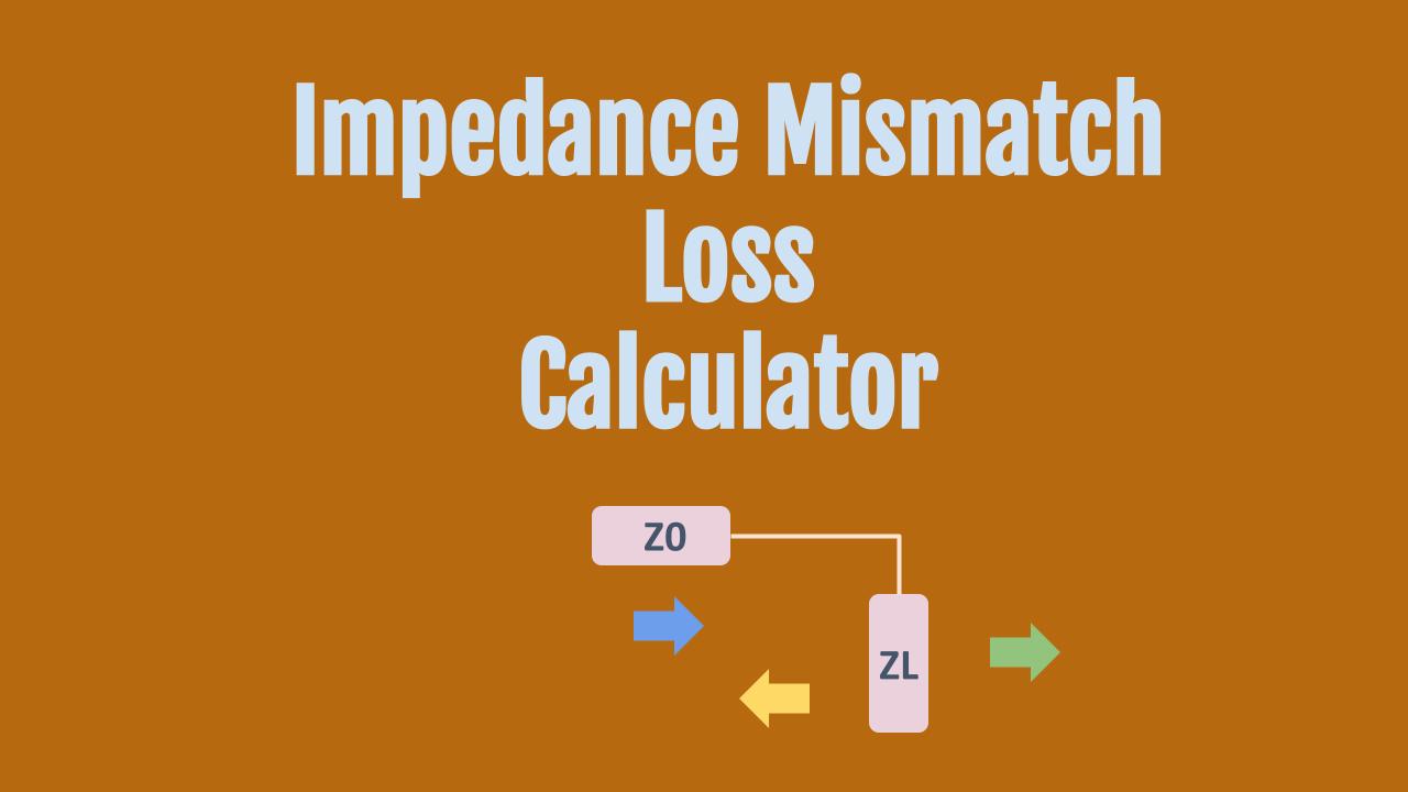
This tool uses the impedance of the source and load to calculate the impedance mismatch.
It also calculates
- Reflection Coefficient
- VSWR (Voltage Standing Wave Ratio)
- Return loss
- Mismatch loss
- Forward power
- Reflected power
Formula
Source Impedance = Z0
Complex Load Impedance = R + j*X
Absolute Load Impedance = √(R2 + X2)
Γ = √[(R-Z0)2 + X2] / √[(R+Z0)2 + X2]
Mismatch Loss (dB) = -10*Log10(1 – |Γ|2)
Return Loss (dB) = -20*Log10(|Γ|)
Reflected Power (%) = 100*(|Γ|2)
Transmitted Power (%) = 100*(1 – |Γ|2)
Example Calculations
Complex Load
For a source impedance of 50 ohm and complex load impedance of 25 + j*25, the return loss is 7 dB and 20% of the power is reflected back with the balance of 80% transferred forward.
If the source and the load are perfectly matched, the VSWR is 1 and 100% of the power is transferred.
50 ohm – 75 ohm mismatch loss
A question that comes up often in the context of using an amplifier or filter designed for 75 ohm in a 50 ohm system.
In this case, what’s the mismatch loss?
When you use those numbers in the calculator above for the load Impedance = R + j*X with R= 75, X = 0
The mismatch loss is calculated to be 0.18 dB.
As a result of this mismatch, only 4% of the incident power is reflected back, while 96% is transmitted forward.
Background
What is Mismatch Loss?
In radio frequency (RF) circuits, mismatch loss occurs when the impedance of one component (like an antenna, cable, or transmitter) doesn’t match the impedance of another connected component. The ideal situation in RF circuits is to have impedance matching—for example, both the transmitter and the cable should have the same impedance, such as 50 ohms. When they don’t, some of the signal is reflected instead of being fully transmitted, leading to mismatch loss.
In simple terms, mismatch loss is the loss of signal power due to the reflected energy caused by impedance differences in the circuit.
Why Does Mismatch Loss Happen?
RF signals behave like waves. When these waves encounter a change in impedance (for example, from a 50-ohm transmitter to a 75-ohm cable), part of the wave is reflected back instead of traveling forward. The larger the difference in impedance, the more energy gets reflected, resulting in less energy reaching the destination.
Related Calculators
- VSWR to S11 – use this tool to find the S11 (S-parameter at port 1 of a two port network)
- Match 50 ohm to any other impedance (both resistive and reactive circuit options are presented)
